Igbt Based Inverter Circuit Diagram A.power Circuit Diagram
Igbt based inverter circuit diagram Igbt inverter circuit diagram Three phase inverter circuit
Igbt Inverter Circuit Diagram - Wiring Diagram
Igbt inverter Igbt circuit equivalent parasitic Power electronics
Basic structure of igbt
Igbt inverter circuit homemade diagrams schematics typical singlePower circuit diagram of an igbt based single phase full-bridge Igbt inverter circuit example spike means igbts insulated bipolar evs gate transistors renesas courtesy used120° mode inverter – circuit diagram, operation and formula.
Power circuit diagram of an igbt based single phase full-bridge1, three phase inverter circuit Igbt based inverter circuit diagram pdfIgbt inverter circuit diagram pdf.

Igbt transistor bipolar gate circuits insulated igbts bristolwatch
Vi characteristics of igbt explainedIgbt explained obtaining resistor Inverter circuit diagram mode 120 operation phase three bridge power formula shown below figureIgbt inverter circuit diagram.
Inverter circuit diagram using igbt » circuit diagramIgbt inverter circuit diagram pdf Inverter fig5Phase inverter circuit three conduction degree schematics sine inverters circuitdigest switching converter.

Inverter circuit diagram using igbt
A.power circuit diagram of an igbt based single phase fullbridgeIgbt inverter circuit Igbt circuit exampleIgbt circuit example.
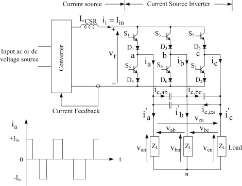
High-power igbt module package structure and equivalent circuit inCircuit diagram of the igbt based current source inverter... Igbt based inverter circuit diagram3: a three-phase igbt-inverter with dc source..

Inverter igbt
Inverter igbt induction coil parallelA spike in evs means a spike in insulated gate bipolar transistors Igbt inverter circuit diagramIgbt inverter.
Igbt based inverter circuit diagramIgbt inverter wiring danyk sg3525 Igbt inverter control circuitInverter igbt implementation microgrid.

3-phase igbt inverter circuit diagram
Igbt module inverter circuit diagramHomemade inverter Single phase inverter circuit with igbtInsulated gate bipolar transistor igbt circuits tutorial.
Igbt inverter circuit diagram pdfSingle phase igbt inverter. .


3: A three-phase IGBT-inverter with DC source. | Download Scientific

Insulated Gate Bipolar Transistor IGBT Circuits Tutorial

igbt inverter circuit diagram - Diagram Board

Three Phase Inverter Circuit - 120 Degree and 180 Degree Conduction
Igbt Based Inverter Circuit Diagram Pdf - Wiring Diagram

Circuit diagram of the IGBT based current source inverter... | Download

Igbt Inverter Circuit Diagram - Wiring Diagram